.................................................................................................................................................................................................................................................................................................................................
TECHNICAL INFORMATION
Click on desired heading to jump to selection
6.0 CASTOR TERMINOLOGY / DEFINITIONS
10.0 WHEEL TERMINOLOGY / DEFINITIONS
All dimensions are in mm and all loadings are in kg unless stated.
Working conditions vary enormously with regard to both the type of floor and the
severity of the application. Load ratings are based on intermittent use on normal truck
or trolley applications. Special conditions may apply under any of the following
applications or hazards:
- Uneven floor surface.
- Ramps, cracks, gullies, door guide rails.
- Track or turntable use.
- Power towing or driven wheels and rollers.
- Any application other than manually propelled truck and trolley use.
It may be appropriate, in certain circumstances, to select a castor or wheel with a load
capacity much greater than appears necessary, please ask our technical sales team
for assistance in product selection.
All moving parts are liberally treated with a high quality grease. This forms a protective
layer which minimises wear by metal to metal contact. Many swivel castors are fitted
with swivel head seals helping to reduce maintenance to a minimum. Where
lubrication is necessary, this should be carried out using a pressure oil gun, taking
care to ensure that the lubricant reaches the king pin head on single ball race castors.
In addition, heavier duty castors and wheels are often fitted with grease nipples and/or
dimpled and drilled axle bolts for replenishment purposes under arduous working
conditions.
Nylon wheel bushes are virtually self-lubricating but will benefit from occasional
lubrication, particularly in very dusty conditions.
A general purpose lithium based grease is used in most castors with a normal
operating temperature range of -30c to +130c.
3.1 Low temperatures
In low temperatures, the consistency of the grease increases up to a point where the
swivel and rolling performance is reduced. For low temperature applications it is
recommended that a double ball race castor is used and fitted with low temperature
grease. Please ask for details.
3.2 High temperatures
In high temperature applications the grease will operate satisfactorily but will need
regular replenishment. This particularly applies in forced draught ovens where the oil
component of grease can be volatilised causing carburisation. Castors fitted with high
temperature wheels and grease are detailed in the Special Application Castors
catalogue. High temperature wheels are listed in the Special Application Wheels
catalogue. Please request a copy.
In general, castors can be sub-divided into two main types:
4.1 Pressed steel
Pressed steel castors incorporate single or double ball bearing swivel race way
construction. The balls run in tracks formed in the fork and top plate pressings which
are secured together by a heavily riveted steel king pin.

4.2 Fabricated steel
Usually consisting of precision machined heavy steel forgings housing combinations
of tapered roller or ball bearing races. The fork legs are usually securely welded to the
swivel head forging giving an extremely strong construction suitable for heavy loads.

Castor applications can be divided into two main categories:
5.1 Castors for use on trucks, trolleys, trailers etc. and used as a means of
transportation (i.e. loaded with goods and regularly moved from one place to another).
It is essential that castors should have the lowest tractive resistance and be able to
swivel freely so that the trolley can be manoeuvred without too much effort. To achieve
this, wheels should be at least 100mm in diameter and preferably 150mm or more,
regardless of the rated load capacity.
5.2 Castors fitted to equipment enabling it to be delivered to the place of use allowing
occasional movement over short distances. Smaller castors may well be suitable and
are often used at their full capacity.
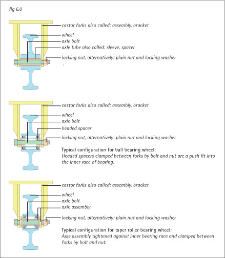
6.0 CASTOR TERMINOLOGY / DEFINITIONS (fig 6.0)
A castor consists of a wheel fitted into swivelling or non-swivelling forks. The wheel is
usually retained between the castor forks using a simple axle set. Some castor
components are described using differing terms by various manufacturers.
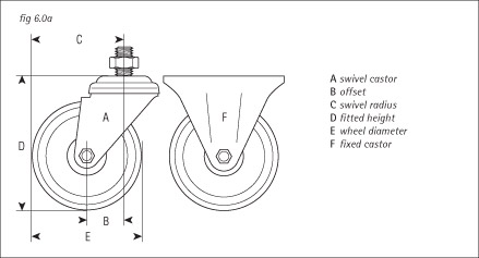
6.1 Swivel castors (fig 6.0a)
A housing containing a wheel which is free to swivel without restriction about the
vertical axis of the swivel bearing with the castor wheel axle offset.
6.2 Fixed castors (fig 6.0a)
A housing containing a wheel which is not to swivel about its vertical axis.
6.3 Wheels
A revolving centre rotating freely on an axle of which the external part (in contact with
the ground) can be constituted by the material of the wheel itself or by a tyre of various
other materials.
6.4 Offset (fig 6.0a)
The horizontal distance between the centre of the wheel axle and the vertical axis of
the swivel bearing. Also known as the trail.
6.5 Swivel radius (fig 6.0a)
Usually the horizontal distance between the outside edge of the wheel and the vertical
axis of the swivel bearing. This can be increased by fitment a brake whose operating
pedal may protrude beyond the outside edge of the wheel.
6.6 Fitted height (fig 6.0a)
The height by which a piece of equipment will be raised by fitting a castor. In the case
of certain fixing types, not necessarily the overall height of the castor (see diagram).
6.7 Wheel diameter (fig 6.0a)
The overall diameter of the wheel (including tyre, if fitted).
6.8 Tractive resistance
The effort required to move a piece of equipment fitted with castors or wheels. It is
vitally important to be able to predict the amount of effort required to either push a truck
in a straight line or to manoeuvre it in tight spaces. When this information is known it
should be possible to calculate the number of personnel required to move and control
the truck in normal workshop conditions. Tractive resistance is usually expressed as a
percentage of the total load to be carried and an approximate guide is as follows:
Hard tread wheels Less than 1%
Polyurethane tyred wheels Approximately 2%
Rubber tyred wheels Approximately 3.5%
This guide is based upon 200mm diameter roller bearing wheels. It should be
remembered that a typical human being is capable of maintaining a horizontal force of
approximately 12kgf increasing to about 18kgf from a standing start. Polyurethane
wheels if left standing under full load for a substantial length of time could require at
least twice the force to initiate movement, its tractive resistance will increase
momentarily up to about seven times the figure given above.
The means by which a castor is fitted to the equipment. The main types are as follows:
7.1 Plate fixing (fig 7.1)
Normally a rectangular plate with four fixing holes (exceptions include 3 hole
triangular plate and 2 hole rectangular plate. ISO 2184 sets out a range of
standardised fixing hole centres as follows:
Class 2: 80mm x 60mm
Class 3: 105mm x 80mm
Class 4: 140mm x 105mm
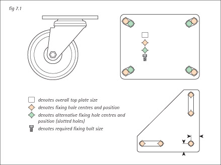
While most products conform to these standards, in some cases fixing holes are
elongated to allow for fitting at alternative hole centres such as those to the DIN
standard or popular North American sizes. Top plate diagrams shown in the catalogue
clearly illustrate hole sizes and positions. Customers are advised to fit to the ISO
standards wherever possible and avoid placing bolt anywhere other than at the end of
slotted holes.
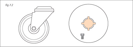
7.2 Bolt hole / single bolt fixing (fig 7.2)
A single hole positioned in the centre of a circular top plate, suitable for fitting a loose
bolt from beneath the swivel head or fixing to a stud attached to the equipment.
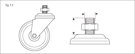
7.3 Threaded stem fixing (fig 7.3)
A fixed stud attached to the castor swivel head. Usually supplied with a loose nut.
Check for availability.
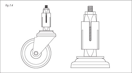
7.4 Expanding adaptor (fig 7.4)
For fixing into square or round tube. Secured by tightening head of hexagon or allen
headed bolt concealed beneath swivel head of castor.
Fitting an expander (fig 7.4a):
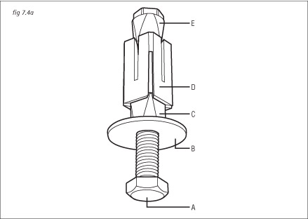
i. Assemble the bolt (A) to the castor so that the bolt head is inside the swivel head.
i.e. Thread protruding from top of castor.
ii. Slide washer (B) over bolt.
iii. Slide bottom cone with plain hole (C) over bolt so that the smaller square end is
facing up.
iv. Slide sleeve (D) over the bolt. The sleeve is the same at each end so orientation is
not required.
v. Align flats on bottom cone with the flats on inside of sleeve.
vi. Screw top cone with threaded hole (E) down bolt so that the small square end
aligns with flats on inside of sleeve. When correctly fitted, sleeve and cones rotate
together and are in line but loose and ready for fixing.
To fix the castor with expander assembly, offer up to tube and push expander
assembly fully home. i.e. castor is in contact with base of tube. Tighten the bolt to a
maximum of 10Nm for M12 bolt or 8Nm for M10 bolts and ensure the castor is securely
fitted.
7.5 Furniture fixings (fig 7.5)
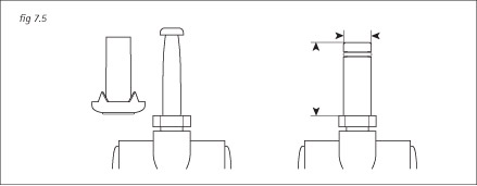
Peg and socket to suit drilled hole in wood or push-fit circlip stem for hole in metal
e.g. chair base. Commonly available with ball type or twin wheel furniture castors.
Castors are available fitted with a wide variety of adaptations to meet the needs
oindividual applications:
8.1 Wheel brake (fig 8.1)
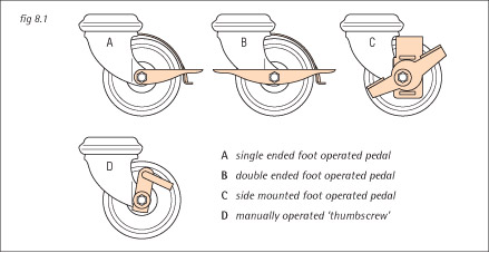
A single or double ended foot operated pedal brings a metal pad into contact with the
tread of the wheel which acts as a parking brake. Alternatively, a manually operated
cranked pin or ëthumbscrewí can be tightened against the wheel centre to achieve a
similar effect.
8.2 Total stop brake (fig 8.2)
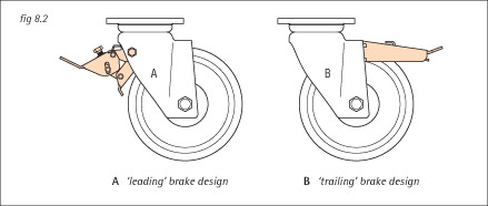
Also called combined swivel and wheel brake. A foot operated pedal simultaneously
brakes the wheel and locks the swivel head in any position. Total stop brake
mechanisms are fitted in either a ëleadingí or ëtrailingí position.
8.3 Directional lock (fig 8.3)
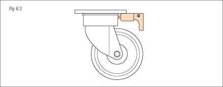
A hand or foot operated lever locks the castor into a fixed position. Some castor types
are available with 2-station (180∞) locks and others with 4-station (90∞) locks. Care
should be taken when using a 4-station lock to ensure that if the lever is left in the ON
position but not engaged during general use, the castor does not subsequently lock at
90 degrees to the direction of travel. This could cause a sudden swerve or damage to
the castor and wheel. Directional locks are supplied welded or in kit form depending
upon castor series.
8.4 Swivel seal / threadguards (fig 8.4)
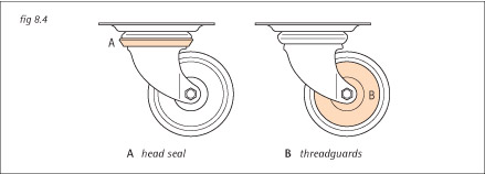
Also called head seal. Usually rubber, where available a head seal can prevent
ingress of dirt and and dust into the castorís swivel head.
Most commonly used in the textile industry, threadguards help to prevent an
accumulation of thread from binding the wheel.
In general, wheels can be sub-divided into two main types:
9.1 Resilient tread wheels
Resilient or soft tread (tyred) wheels, such as rubber or polyurethane, give the ultimate
in quietness and floor protection but introduce a penalty from the point of view of ease
of movement, as the tractive resistance or effort required to move the equipment can
generally be up to three times that of the equivalent sized hard tread wheels.
Polyurethane, however, has the remarkable property of being able to carry loads
approaching those of cast iron, and has a great resistance to tearing and abrasive
wear (many times the life of rubber). It also has a lower tractive resistance than rubber
for the same load and is impervious to mineral oils and greases. For many high load
manual applications soft tread wheels can be ruled out as, although they may be
capable of carrying a high load, the force required to move the equipment would be
excessive.
However, the quiet running and floor protecting properties of a resilient tread make it
particularly suitable for power towing applications.
9.2 Hard tread wheels
In the range of hard tread (or untyred) wheels it is usual to consider the cast iron wheel
as a basic standard as these are generally the strongest and have the longest life.
They are certainly the easiest to push and in many cases will, therefore, be the first
choice for maximum mobility.
They have the disadvantage, however, of being rather noisy and can sometimes
cause excessive floor wear. As an alternative to cast iron, injection moulded or cast
nylon wheels have been developed. Nylon is unaffected by water and its use in the
wet further enhances its self-lubricating properties. The load capacity of nylon
approaches that of cast iron and these wheels also have the additional advantages of
being quieter running, light in weight and unlikely to cause floor damage. They can be
used in the temperature range -40∞c to +80∞c, although it may be necessary to
derate the load capacity by up to 25% for very arduous conditions. For higher
temperature applications, thermoplastic or phenolic resin wheels are also available.
10.0 WHEEL TERMINOLOGY / DEFINITIONS
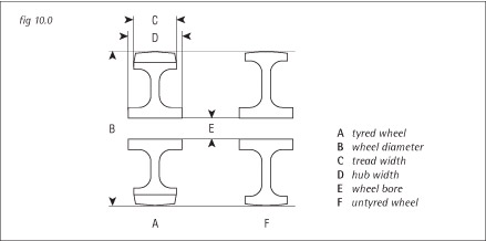
10.1 Wheel diameter (fig 10.0)
The overall diameter of the wheel (including tyre, if fitted).
10.2 Tread width (fig 10.0)
The overall width of the tread of the wheel at its widest point.
10.3 Hub width (fig 10.0)
The overall width of the wheel at its hub
10.4 Bore (fig 10.0)
The inside diameter of the wheel bore. In the case of a wheel fitted with bearings, the
bore represents the inside diameter of the bearing.
Four main types of wheel bearing are available. Plain bearing (plain bore) wheels are
adequate for many applications where maximum mobility is not essential. Roller
bearings do not increase load capacity but keep rolling resistance to a minimum and
prolong working life. Ball journal and taper roller bearings absorb axial loads and are
essential for power towing applications.
11.1 Plain bearing (fig 11.1)
In the case of cast iron wheels and cast iron centred wheels, frequent lubrication is
essential using the grease nipple or drilled hole in axle bolt, if provided. Nylon and
nylon centred wheels have the axle tube greased on assembly and in good working
conditions will run for a very long time without additional lubrication. There is,
however, a risk of squeaking and excessive axle tube wear in dusty and gritty
conditions.

11.2 Roller bearing (fig 11.2)
Roller bearings are greased on assembly and in light duty applications, under normal
working conditions, should not require replenishment.
Castors designed for heavy duty applications are always provided with a means of
replenishing the lubricant in the roller bearing. In cast iron and cast iron centred
wheels, the roller bearing runs on an outer hardened steel split sleeve which gives
extended life and reduced rolling resistance. In wheels with plastic centres, the split
sleeve is unnecessary and is therefore omitted.
11.3 Ball journal bearing (fig 11.3)
Ball journals are ideal for applications where high radial and moderate axial loads
exist, and give very low rolling resistance. The bearings are shielded to retain grease
and exclude grit and dust. A spacer tube between the bearings is used to support the
inner races which are clamped together end-wise on assembly. No adjustment is
necessary. Ball journals are suitable for both manual and low speed power towing
applications.

11.4 Taper roller bearing (fig 11.4)
Precision tapered roller bearings are suitable for the heaviest applications where high
radial and axle loads are present. Bearing cups and cones are hardened for extended
life and the bearing is adjusted on installation to give optimum service life. Seals are
fitted to retain grease and exclude grit, dirt etc., and grease nipples are provided for
replenishment under arduous working conditions.
Where an application may result in contact with, or exposure to chemicals, each
component of the proposed castor or wheel should be checked for compatibility.
For advice on compatibility, please contact our technical sales department with full
details of chemicals present in your application.
13.0 CASTOR AND WHEEL CONFIGURATIONS
In considering various truck and trolley designs, the correct alignment of fixed and
directional lock castors is essential. In accordance with the relevant ISO standard, top
plate fixing holes have a working clearance of 1mm for all bolts up to 12mm and 2mm
for larger sizes. This accommodates minor positional errors in the manufacture of the
trolley but, unfortunately, also allows the castors to be misaligned to the point where
drag and tyre wear could be excessive. It is therefore necessary to correctly align the
castors before the bolts are finally tightened.
13.1 Two swivel / two fixed castors (fig 13.1)

The most practical configuration for industrial use. This solution provides good load
capacity with good manoeuvrability and ensures accurate steering, even on long
straight runs. The trolley should normally be pushed with the fixed castors leading.
13.2 Four swivel castors (fig 13.2)

This arrangement provides good load capacity with excellent manoeuvrability suitable
for winding runs and where side motion is frequently required. However, trolleys with
this configuration may be difficult to guide on straight runs, particularly with heavy
loads and uneven ground. Not recommended for ramps. If two castors are equipped
with directional locks, this arrangement is then suitable for long straight runs, a very
versatile arrangement.
13.3 One swivel / two fixed castors (fig 13.3)

An economical solution for lightly loaded trolleys requiring good manoeuvrability. The
trolley must be fairly small in size and it is essential that the load is evenly distributed
to ensure stability on the unit.
13.4 Three swivel castors (fig 13.4)

This arrangement provides good load capacity with excellent manoeuvrability.
However, equipment with this arrangement will be difficult to guide on straight runs,
particularly over uneven ground. The configuration is ideal for barrel dollies and small
portable machines.
13.5 Four swivel / two fixed castors, centrally pivoting (fig 13.5)

Besides providing a very high load capacity, this arrangement also assures
manoeuvrability and stability. This configuration is best used with longer trolleys
designed to carry heavy loads. The fixed castors could be replaced by axle mounted
wheels and the base of the unit must be of a robust construction. The swivel castors
are mounted in such a way as to pivot the trolley on the central wheels, usually by
packing the fixed castors by approximately 25mm.
13.6 Two swivel / two fixed castors, centrally pivoting (fig 13.6)

This solution provides good load capacity with excellent manoeuvrability in confined
areas. The fixed castors could be replaced by axle mounted wheels. The swivel
castors are mounted in such a way as to pivot the trolley on the central wheels, usually
by packing the fixed castors by approximately 25mm. The load must be evenly
distributed to ensure stability.
13.7 Four fixed castors, centrally pivoting (fig 13.7)

An economical solution for moderate loads suitable for long, straight runs with
occasional changes in direction. The fixed castors could be replaced by axle mounted
wheels. The swivel castors are mounted in such a way as to pivot the trolley on the
central wheels, usually by packing the central fixed castors by approximately 25mm.
The load must be evenly distributed to ensure stability.
14.0 POWER TOWING APPLICATIONS
Most pressed steel castors are designed specifically for manual propulsion. Due to the
greatly increased stresses exerted on various castor components in power towing,
fabricated castors are recommended. Fabricated castors are designed on the
assumption that power towing will take place in good working conditions and at
speeds of up to 6kph.
Obstructions such as kerbs, gullies and even relatively small steps can exert
enormous impact loads which can destroy a castor. Steps such as lift sills, drain
covers and joints in concrete slabs present a particular problem if they are not
approached squarely. An oblique approach will almost certainly result in the castor
turning at right angles to the obstruction instead of turning in such a way that it can
climb over it. In these circumstances the destruction of the castor is inevitable.
As power towing becomes more common, it is often desirable to tow a number of
trucks or trailers one behind the other. Towing trailers in train though can exacerbate
the problem as only one castor may have to withstand the force generated by the
mass of the whole train including the tractor.
Traditional turntable axles have often been used in this application but, in addition to
being costly, they have two disadvantages:
- If the turntable is at right angles to the axis of the trucks, stability is greatly reduced
- There is a risk of jack-knifing
Castors are, therefore, becoming very popular for power towing and work satisfactorily
provided suitable precautions are taken. It is essential to obviate ëcutting-iní as this
prevents the use of truck trains in narrow gangways.
14.1 Castor configurations for power towing (fig14.1)
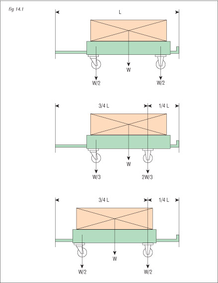
Experience shows that if trucks are rigidly coupled by means of pin couplings at each
end, they will follow the track most accurately if the distance from the fixed castor
centre-line to the rear coupling pin is 25%-33% of the total length of the truck from front
to rear coupling pins.
This can be achieved by moving the fixed castors forward as shown, but this incurs a
penalty in that it reduces the wheelbase and causes the load to be shared
disproportionately between the swivel and fixed castors.
In order to distribute the load evenly, it is advisable to extend the drawbar at the rear of
the truck as shown in the third arrangement.


